The Homopolar Motor Project Experiment
Recently I came across an article on the internet regarding an interesting simple motor: the world's simplest as it was described. This is the homopolar motor.
Homopolar motor set-up
This particular motor is so simple that all you will need is a magnetic field source(usually a powerful permanent magnet), a screw or nail, a power source(usually a battery) and of course some copper to make electrical connections. No slip rings, bearings/bushings or coils of copper involved. It is so simple it can be made under an hour. Hmmmm....sounds interesting to me. So I decided to try make an experimental set-up for myself.
But before that, some additional information is in order. It turns out that this device was actually invented by Michael Faraday himself although he cannot explain at the time the phenomena observed. Just that it works. And here is how it works. If you are not satisfied with my explanation here, just try googling "homopolar motor". You'll get lots of websites offering better and more detailed explanation than mine. I myself does not fully understand the mechanism.
By way of short explanation, consider having a metal conducting disk which can spin on an axis perpendicular to its plane. Let this axis be a metal conducting shaft at the center of the disk. Now you need to also have a magnetic field through the disk running parallel to the disk shaft. That's where the strong permanent magnet comes in. Now try connecting the positive(or negative ) terminal of a battery to the shaft using copper wire and the other terminal to the edge of the disk. See how the disk starts spinning. Reverse the terminal connection of the battery and the disk spins in the opposite direction. The spinning motion is due to what they call Lorentz forces. I feel I am not qualified to discuss that technical aspect here but wikipedia offers a detailed mathematical explanation.
And now to the fun part....
Below is a picture of the basic materials I will use for the simple project experiment.

The one peso coin (Philippine currency) will serve as the disk. The screw will be the shaft. The small cylinder is a powerful neodymium magnet which will provide the magnetic field.
I will also need the additional items pictured below to complete the experiment.
I will also need the additional items pictured below to complete the experiment.

A small 12volt lead acid battery will provide the power source. And of course alligators clips and copper wire to make electrical connections.
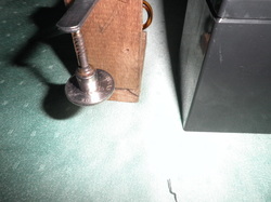
Pictured below is the basic set up I used for the experiment.
Pictured below is the basic set up I used for the experiment.
|
|

|
The coin disk is at the bottom attached to the magnet. The screw is attached to the other side of the magnet and hangs by its point cantilever-like to the metal tweezer. The whole assembly does not fall due to the strong magnetic field of the neodymium magnet.
Below is a short video of the homopolar motor in action.
The contacts is quite jumpy. You can see the sparks when full connection is made. I also noticed the wires becoming hot quickly. Meaning large currents was drawn while running. It is not so surprising as I am actually making an almost shorted connection between the positive and negative terminals of the battery. Resistance along the current path is quite low.
Anyway that's it. I was able to prove to myself the concept really work. In the future I may try making a project based on the principle involved in the homopolar motor. But first I will have to read more on the subject before I try anything more complex.:)
Anyway that's it. I was able to prove to myself the concept really work. In the future I may try making a project based on the principle involved in the homopolar motor. But first I will have to read more on the subject before I try anything more complex.:)
