The PMG(permanent magnet generator) is my first attempt at developing a project that can help promote the use of renewable energy sources by regular people like you and me.
In the Philippines where the price of electricty is quite high, it is wise to start generating at least a small portion of the electricity needs at home through renewable energy. In a recent news article, the Philippines is recorded as having the highest power rates in Asia and number five in the world. On top of that, there is always the specter of sudden power outages from natural calamities such as strong typhoons. Or even more frightening a strong earthquake.
In the Philippines where the price of electricty is quite high, it is wise to start generating at least a small portion of the electricity needs at home through renewable energy. In a recent news article, the Philippines is recorded as having the highest power rates in Asia and number five in the world. On top of that, there is always the specter of sudden power outages from natural calamities such as strong typhoons. Or even more frightening a strong earthquake.
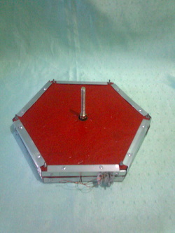
PMG
The PMG(see picture at left) I developed is an effort to start in the use of renewable energy. It is capable of 150 watts of power output. It has three phase power output . In tests using a hand drill to turn the shaft and a 12 volt car battery as load, output current jumps to more than 10-12 amps. But the unit is capable of up to 18 amperes. Without any load, the shaft exhibits no cogging. Thus it is ideal for small wind turbine application. It is also quite light in weight (~2.25 kg). The body is fiber reinforced plastic with aluminum reinforcement.
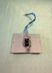
Rectifier
As the unit outputs three-phase power, there is a need for a rectifier (see picture at left). This device converts 3phase AC to direct current suitable for charging batteries (e.g. lead acid types) in a renewable energy set up.
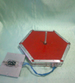
PMG with rectifier
Pictured at the left is the PMG with the rectifier already attached.
I have mentioned before that the PMG is suitable for wind turbine application. However, in my case I live in Quezon City in the Philippines. An area where wind is seldom strong enough for a wind turbine to be worth setting up. I have to find a different way to harness renewable energy from the PMG even if only a small portion of its potential. That is why I thought of installing it in a bicycle. Rig a chain and sprocket set-up so I can turn the shaft while pedaling in a stationary stand. That way I can at least charge lead acid batteries or other rechargeable types while exercising on the stationary bike. See some pictures below of the PMG already mounted in the bike.

Front view of mounted PMG with attached chain and sprocket on shaft.

Another view of the mounted PMG. The rectifier can be seen at the back.

Back view of the mounted PMG. The rectifier and the output cables are clearly visible.
Admittedly my bike set-up cannot provide the needed RPM and shaft torque to provide large power for current hungry loads. However it can generate voltage of up to 5 volts. I made a small switch mode booster to boost the voltage upwards so I can charge even up to 48 volts batteries. The output from the booster goes up to 150volts. Admittedly it was an overkill but I am new to designing SMPS circuits so even a simple booster is an achievement for me. You can see the small booster circuit to the left of the rectifier.
Below are some short videos of the PMG outputting power. Two videos has the PMG lighting 12 volt car bulbs and a CFL. Another video has the PMG lighting a small bulb while the bike is being pedalled.
Below are some short videos of the PMG outputting power. Two videos has the PMG lighting 12 volt car bulbs and a CFL. Another video has the PMG lighting a small bulb while the bike is being pedalled.
In the video above, I used a hand drill to turn the shaft. As I said the PMG requires high torque to provide higher currents to loads. The bike cannot provide that. It is quite stiff to turn the shaft when a load is connected. I just set the drill to lowest setting and tried to control my fingers on the switch so it wouldn't turn so fast. Higher RPM outputs higher current which might bust the bulbs. In the video below the PMG is powering a CFL.
Again I needed to use a hand drill for the demonstration. Notice the circuit on the breadboard beside the CFL. It is a driver circuit for an inverter which is connected to a small transformer behind the breadboard. The CFL uses 220volt AC while the PMG output is just DC. So we needed the inverter to provide the right form of power to the CFL
In the third video below, the PMG is being turned by pedal. As I said before the bike set-up cannot provide high RPM and torque to deliver high currents (and thus power). But then it can still harness even a small portion of the PMG's potential output. I attached a small bulb to the cables as a load. You can clearly see it lighting up as I turn the pedal.
I plan to use the stationary bike to charge 12 volt lead acid battery since I added a booster circuit that pumps the voltage up to even 150 volts DC. Then the battery, with the appropriate inverter can power 220volt AC household devices. This should be a good start to using renewable energy for me.
This is all and I hope you enjoyed scrolling through this page devoted to the permanent magnet generator. Thank you.
This is all and I hope you enjoyed scrolling through this page devoted to the permanent magnet generator. Thank you.
_______________________________________________________________________
UPDATE!!! 02/04/2012
It is now some time since I first published these webpages. Since then I have received some feedbacks/inquiries regarding a "low RPM" PMG. By this they mean a PMG that can generate sufficient voltage by itself(e.g. 12volt DC) even when the shaft is not rotating very fast. This sort of challenged me to find a way to make this PMG meet or at least come as close as I can to the criteria for a low RPM PMG.
I know somehow I can make some changes on how I assemble the PMG in such as a way as to increase its output voltage without any real internal changes in its construction. The key is how I make the final coil connections. It is easy to do that. However, I still want to have the option of choosing the standard connection if I want to. So then the simplest solution I could think of is to make the final connections "outside" the PMG case. This can be implemented using a terminal block. All final wire coil ends are screwed on to the terminal block. Then using jumper wires, I can choose whether to connect the coils the standard way or the low RPM configuration.
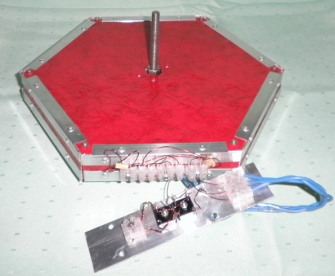
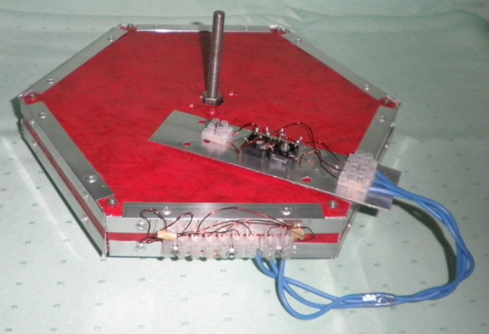
Below are a couple of pictures of the new PMG with the terminal block clearly visible and a rectifier attached also. It is connected the low rpm way.
I know somehow I can make some changes on how I assemble the PMG in such as a way as to increase its output voltage without any real internal changes in its construction. The key is how I make the final coil connections. It is easy to do that. However, I still want to have the option of choosing the standard connection if I want to. So then the simplest solution I could think of is to make the final connections "outside" the PMG case. This can be implemented using a terminal block. All final wire coil ends are screwed on to the terminal block. Then using jumper wires, I can choose whether to connect the coils the standard way or the low RPM configuration.
Below are a couple of pictures of the new PMG with the terminal block clearly visible and a rectifier attached also. It is connected the low rpm way.
|
|
|
|
Trial turning of the shaft using my bare fingers, the PMG produces a steady 3-4 volts DC at a rotation speed of about 1 rev/sec or about 60RPM. Without any load, I can easily produce 15-16 volts DC with my fingers turning the shaft. That's as close to low RPM criteria as I can get this PMG to be.
To check if output with load is significantly affected, I also tested with various loads. Below are some videos of the low RPM PMG in action.
The first video is again using a couple of 12 volt DC carbulbs as load.
The second video below is the low RPM PMG powering a 220volt AC incandescent bulb.
The third video below is the low RPM PMG lighting a CFL.
This is all for now and I hope you enjoyed the update.
UPDATE: 02/27/12
I just added this video below of the Low RPM option of the PMG lighting a small bulb using only my hand. Previously I could not light even a small bulb as a load since the shaft becomes difficult to turn once there is a load. To overcome this, I installed a disk(actually a bike chain ring), to give me more torque to turn the shaft. Now at least I can show I can produce some power even by turning the shaft manually.
